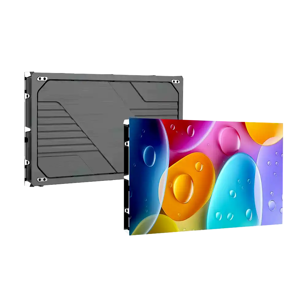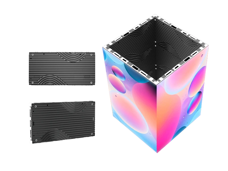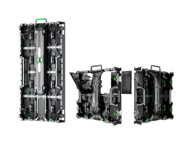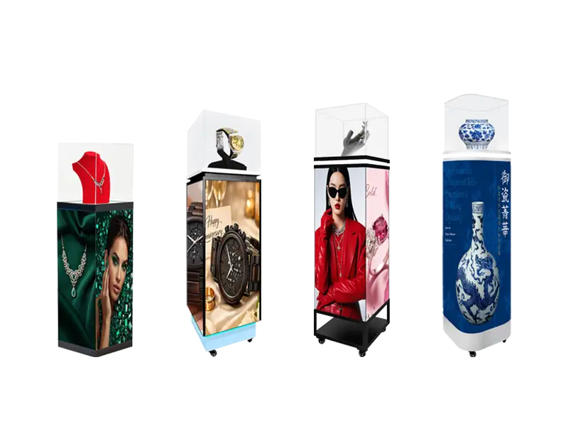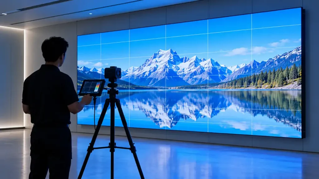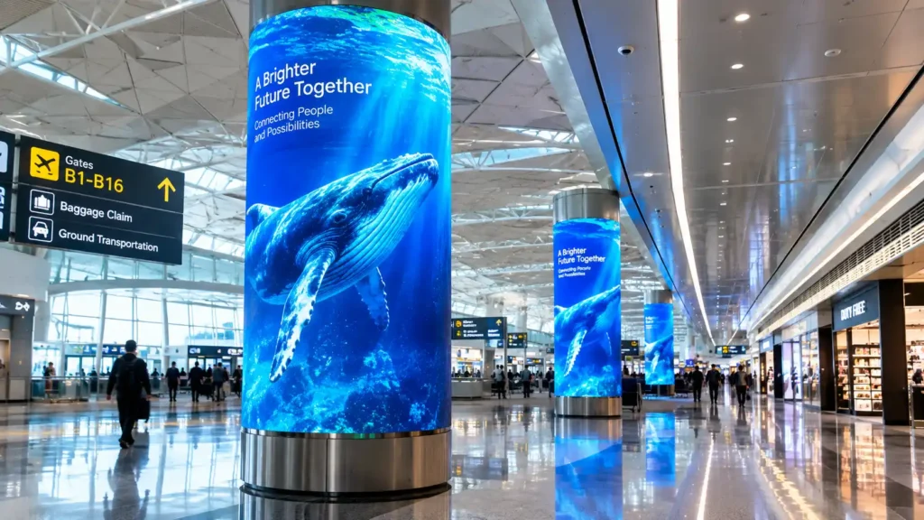
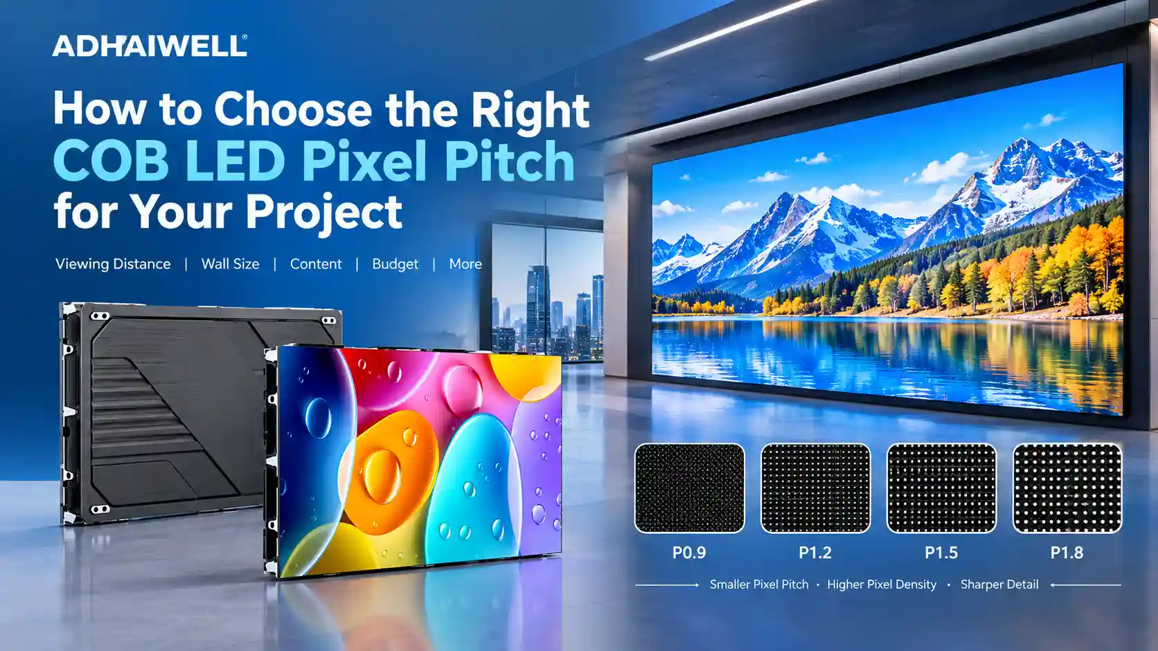
Choosing the right COB LED pixel pitch depends on how close the audience will sit, how much detail the content requires, the physical dimensions of the LED wall, and the available project budget. For very close-viewing environments, P0.9 may be appropriate. P1.2 is a practical option for many high-detail indoor applications, while P1.5 and P1.8 can provide a suitable balance between image clarity, screen size, and cost for larger viewing environments.
However, a smaller pixel pitch is not automatically the best choice. Buyers should evaluate the actual viewing conditions, native resolution requirements, display specifications, installation constraints, and maintenance arrangements before selecting a COB LED display.
The following table provides an initial comparison of four common fine-pitch COB LED display options.
| COB LED Pixel Pitch | Typical Application | Main Selection Consideration |
|---|---|---|
| P0.9 | High-end control rooms, close-viewing corporate displays, premium visualization environments | High pixel density for detailed content viewed at short distances |
| P1.2 | Control rooms, meeting rooms, broadcast environments, high-detail indoor video walls | A balance of image detail, screen dimensions, and project cost |
| P1.5 | Corporate lobbies, conference facilities, command centers, commercial display walls | A practical choice for medium-sized indoor installations |
| P1.8 | Larger indoor video walls, reception areas, exhibition spaces, commercial environments | Lower pixel density than finer pitches, potentially reducing the cost of a large display |
These applications are general guidelines rather than fixed rules. The most suitable COB LED pixel pitch depends on audience distance, content type, screen dimensions, visual comfort, and the specifications of the complete display system.
Key Takeaways
- Pixel pitch sets pixel density, but the number a buyer can verify is the cabinet pixel count — nominal model names such as P0.9 are rounded labels for a finer grid.
- The familiar rule of 1 m of viewing distance per millimetre of pitch is a floor for casual viewing, not a comfort specification. For dashboards and text, the usable distance is roughly 3.5× that floor.
- At a fixed pitch, resolution is decided by wall size. The same 6.0 × 3.375 m wall is exactly native 4K at P1.5 and 6,400 × 3,600 at P0.9.
- Pitch alone does not determine image quality: brightness, grey depth, refresh rate, uniformity calibration and driver electronics separate two walls of identical pitch by more than one pitch step does.
- COB reached about 16% of LED display industry output value in 2025 and is projected to reach 36% by 2030 (Hangjia Research, 2026), which has moved the decision from “can we afford fine pitch” to “which fine pitch does this room require”.
What Is Pixel Pitch in a COB LED Display?
Pixel pitch is the distance in millimetres from the centre of one pixel to the centre of the next, and in a COB display it is fixed at the moment of packaging: the LED chips are bonded directly to the PCB and sealed under a single encapsulating surface, so the pitch cannot be altered, upgraded or repaired at that level later.
COB stands for Chip-on-Board, a packaging technology in which LED chips are mounted directly onto a substrate and protected by a surface coating or encapsulation layer, depending on the product design. COB technology is often used in fine-pitch indoor LED displays where pixel protection, surface durability, and close-viewing performance are important.
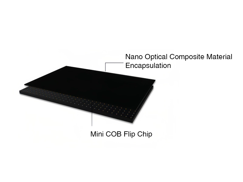
- COB means chip-on-board. Bare LED chips sit on the board and are encapsulated as one surface, instead of three discrete lamp packages being soldered per pixel. That structure is what makes pitches below 1.2 mm dependable at volume — there are no exposed lamp legs to bend or shear.
- Pitch is a physical dimension, not a resolution. It describes spacing. Resolution comes from how many of those spacings fit across the wall.
- The conversion is simple and worth memorising: pixels per metre = 1,000 ÷ pitch in mm; pixels per m² = (1,000 ÷ pitch)². At P1.2 the built pitch is 1.25 mm, so 800 px/m and 640,000 px/m².
- Terminology around it — nits, grey depth, refresh — matters as much as the pitch figure. If any of those units are unfamiliar, our LED display terminology guide covering pixel pitch and nits sets them out in one pass.
How pixel pitch affects pixel density and image detail
Pixel pitch directly affects the number of pixels that can fit into a given area.
A smaller pitch fits more pixels within the same screen dimensions, improving the reproduction of fine text, thin lines, detailed graphics, and high-resolution visual content.
Density falls with the square of the pitch, which is why small pitch changes have large effects on what a wall can show. Moving from P1.2 to P1.8 does not reduce pixel density by a third; it cuts it by 56%, from 640,000 to 284,444 pixels per square metre.
| Pitch | Effective pitch | Pixels per metre | Pixels per m² | Relative density vs P1.2 |
|---|---|---|---|---|
| P0.9 | 0.9375 mm | 1,067 | 1,137,778 | 1.78× |
| P1.2 | 1.25 mm | 800 | 640,000 | 1.00× |
| P1.5 | 1.5625 mm | 640 | 409,600 | 0.64× |
| P1.8 | 1.875 mm | 533 | 284,444 | 0.44× |
Two consequences follow, and both are routinely missed in tenders:
- Detail is a property of total pixel count, not pitch. For a display with a fixed physical width and height, reducing pixel pitch increases its native pixel resolution. This can be particularly useful in control rooms, corporate meeting spaces, and visualization environments where operators or viewers need to examine detailed information.
- The same pixel count costs more at a finer pitch. Density falls with the square of the pitch, which is why small pitch changes have large effects on what a wall can show. Moving from P1.2 to P1.8 does not reduce pixel density by a third; it cuts it by 56%, from 640,000 to 284,444 pixels per square metre.

Why pixel pitch alone does not determine display quality
Two walls can share a pitch and still look nothing alike, because pitch only governs how finely the image is sampled — everything that happens after sampling governs how it looks. On Adhaiwell’s COB platform, P0.9 through P1.8 are identical in brightness band (600–800 nits), refresh rate (3,840–7,680 Hz), grey depth (14/16-bit), viewing angle (up to 160°–170°) and front-maintenance architecture; the pitch change alters resolution and nothing else in that list.
Important factors include:
- Contrast and black level: These affect the visibility of dark scenes, fine details, and text against dark backgrounds.
- Brightness and grayscale performance: These influence image visibility and tonal detail under different indoor lighting conditions.
- Color uniformity: Consistent color reproduction helps prevent visible differences between areas of a large video wall.
- Refresh rate and processing: These influence motion reproduction, signal compatibility, and camera performance in applications such as broadcast studios.
- Calibration and installation: Cabinet alignment, module consistency, and color calibration contribute to a uniform image across the wall.
- Content resolution: Low-resolution source material cannot reveal all the benefits of a high-density display.
For this reason, buyers should compare complete product specifications and request representative content demonstrations instead of selecting a display based only on its pixel pitch.
P0.9 vs P1.2 vs P1.5 vs P1.8 COB LED Displays
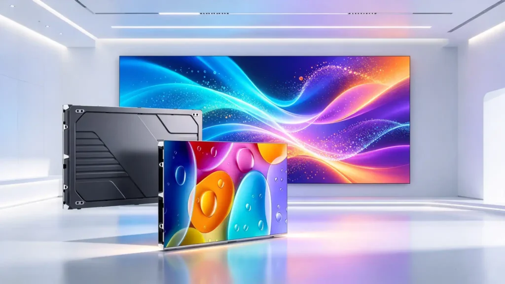
P0.9 buys resolution inside a tight footprint, P1.2 balances resolution against cost for the rooms most projects actually contain, and P1.5 and P1.8 buy area instead of density for audiences that sit further back. The four are not a quality ladder — they are four positions on a trade between pixels per square metre and cost per square metre.
The current P0.9–P1.8 COB LED display options share the 16:9 cabinet and the flip-chip COB build, so a project can move between pitches late in design without re-engineering the mounting structure — only the cabinet count and the pixel budget change.
P0.9 for very close-viewing applications
P0.9 is the right answer when the constraint is space, not budget: an operator desk 1.5 m from a 3.5 m wide wall, an executive briefing room where the screen must fit between two structural columns, a broadcast set where the camera sits inside 2 m during a close shot. At 1,137,778 pixels per m² it packs a native 4K canvas into 3.6 × 2.03 m using 36 cabinets.
- Specify it for the closest seat, not the average seat. If the nearest viewer is beyond 2.5 m, the extra density is being paid for and not used.
- Budget the control chain, not just the panels. P0.9 carries 1.78× the pixel load of P1.2 across the same area, so receiving-card count, sender capacity and refresh headroom all rise with it.
- Plan heat and access early. Higher pixel density concentrates drive electronics into less area; front-service modules help, but the wall cavity still needs airflow designed into it.
P1.2 for fine-detail indoor displays
P1.2 is the pitch most indoor projects should start from, because it is the point where dashboard text, 1-pixel chart lines and video conferencing faces all resolve cleanly at normal boardroom distance while keeping a 4K canvas inside 4.8 × 2.70 m — 64 cabinets, 12.96 m². That mix of density and buildable size is why it remains the largest COB shipment pitch: Hangjia Research’s 2026 COB/MIP survey reports P1.2 as the volume leader, with P1.5 and above forecast to take about 60% of COB shipments by 2030 as their cost per square metre falls.
- Boardrooms and command centres: 2–4 m viewing, 16:9 content, camera and conferencing work.
- Premium retail and showrooms: close inspection of product detail without a visible pixel grid.
- Sanctuaries and auditoriums: P1.2 for the front rows, P1.5 further back — a mixed-pitch sanctuary is legitimate when the platform is the same.
P1.5 and P1.8 for larger indoor viewing environments
P1.5 and P1.8 are the economically correct choices once the audience sits beyond about 4 m, because the pixel count a room can actually resolve stops growing while the cost of density keeps rising. A 6.0 × 3.375 m wall gives exactly 3,840 × 2,160 at P1.5 — native 4K, 100 cabinets, 20.25 m² — and a 7.2 × 4.05 m wall gives 3,840 × 2,160 at P1.8, 144 cabinets, 29.16 m².
- P1.5 fits conference rooms, churches, lecture theatres, hotel ballrooms and large showrooms where the front row is 4–6 m back.
- P1.8 fits the same rooms with deeper seating, plus retail and hospitality walls where the content is graphic rather than textual.
- Both keep the COB advantages — sealed surface, high contrast, front service — so choosing a coarser pitch is not a downgrade in technology, only in density.
- The market is moving this way. Hangjia Research projects COB monthly shipments of 220,000–240,000 m² by 2030 with P1.5 and above at about 60% of that volume, driven by P1.5+ COB overtaking SMD on cost performance.
Compare specifications, not just model names
The model name on a quotation is a rounded label; the number that determines resolution is the cabinet pixel count, and buyers should ask for it in writing. In a 600 × 337.5 mm 16:9 cabinet the pixel counts work out to 640 × 360, 480 × 270, 384 × 216 and 320 × 180, which correspond to effective pitches of 0.9375, 1.25, 1.5625 and 1.875 mm.
- The arithmetic is the proof. 600 mm ÷ 0.9 mm gives 666.7 pixels — not an integer, so a cabinet cannot be exactly 0.9 mm across a 600 mm module. The label is rounded; the grid is not.
- This is not a trick by any one supplier. Quarter-step pitches (0.9375, 1.25, 1.5625, 1.875) are what let cabinets divide cleanly into 2K, 4K and 8K canvases, and the industry names them 0.9, 1.2, 1.5 and 1.8 for short.
- Confirm the final cabinet resolution on the project datasheet, because chip package and driver choices can change the module layout even at a fixed nominal pitch. The figures here are derived from the published 600 × 337.5 mm cabinet, not quoted from a datasheet.
- What to put in the specification: cabinet resolution in pixels, total wall resolution, cabinet quantity and layout, LED chip brand and binning, driver IC, refresh rate, grey depth, brightness with the drive current it was measured at, and measured power per m².
- Where COB is not the answer: if the project needs a broad pitch range, component-level repair by a local technician, or the lowest cost per square metre at P2.5 and above, a fine-pitch SMD indoor LED video wall is the more sensible route. COB earns its premium below about P1.5.
How to Match Pixel Pitch to Viewing Distance
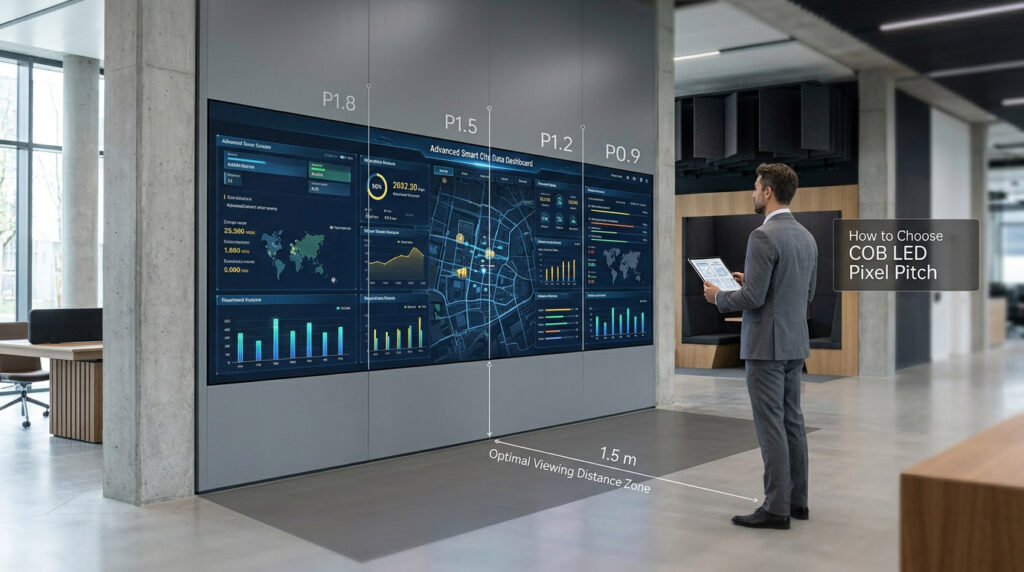
Start with the industry rule of about 1 m of viewing distance per millimetre of pitch, then raise the distance until the pixel grid stops being visible for the content that will actually run — for text-heavy and camera-facing applications that usually means two to three times the rule, not the rule itself.
The rule survives because it is easy to remember and roughly right for casual viewing of large graphic content. It breaks down for the three cases that dominate real indoor projects: dashboards read at 1-pixel line weights, faces on a video call, and anything a broadcast camera points at.
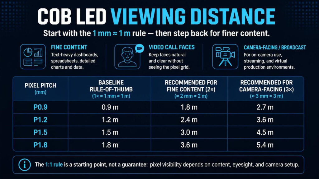
| Pitch | Rule-of-thumb floor (1 m per mm) | Grid becomes invisible (20/20 acuity) | Recommended band for video and presentations | Recommended band for dashboards and text |
|---|---|---|---|---|
| P0.9 | 0.9 m | 3.2 m | 1.8–3.2 m | 2.6–3.2 m |
| P1.2 | 1.2 m | 4.3 m | 2.4–4.3 m | 3.4–4.3 m |
| P1.5 | 1.5 m | 5.4 m | 3.0–5.4 m | 4.3–5.4 m |
| P1.8 | 1.8 m | 6.4 m | 3.6–6.4 m | 5.1–6.4 m |
The upper bound in each recommended band is the acuity distance — beyond it, a finer pitch adds nothing the eye can use. A viewer further back than the band is not a problem; a viewer closer than its lower bound is.
Audience distance and typical content
“Grid becomes invisible” is a calculated figure, not a marketing one: standard 20/20 acuity resolves about one arcminute of arc, which for a display means the eye can no longer separate individual pixels at roughly 3,438 times the pitch in millimetres. That is 3.2 m at P0.9 and 6.4 m at P1.8 — about 3.5 times the rule-of-thumb floor in both cases.
- Video and presentation content tolerates a visible grid. Faces, motion and large type read acceptably from about 2× the floor; the audience perceives a screen, not a lattice.
- Dashboards and text do not. A 1-pixel grid line or a 12-pixel font at 1 m per mm of pitch lands near the edge of legibility and produces the eye strain that generates complaints two months after handover. Design these walls at or beyond the acuity distance.
- Broadcast and virtual production add a camera constraint. Moiré and scan artefacts appear when the camera’s sampling interacts with the LED grid; specify at the camera’s working distance and at 3,840 Hz or higher, and test with the actual camera before sign-off.
- Measure the nearest seat, not the room’s nominal capacity. Front-row chairs, wheelchair positions, standing room at the back of a boardroom, a presenter who walks to the screen — each can halve the effective distance the design assumed.
Why viewing-distance rules are only starting points
Because a rule built from one variable cannot hold four: screen size, content, eyesight and the room all move the answer, and the rule silently assumes all four are average. Two projects can follow the same table and end up with one wall that looks sharp and one that looks soft.
- Screen size decides whether the distance is even usable. Pixel angular size depends only on pitch and distance, but whether a viewer can take in the whole image at that distance depends on wall size. A 3 m wide wall at 5 m is a detail window; a 7 m wide wall at 5 m is an immersive wall. Same pixels per degree, different job.
- Acuity is a threshold, not a comfort level. 20/20 is a screening standard; a meaningful share of viewers see better, and low-contrast content needs more distance or more grey depth even at nominal acuity.
- Content type moves the target by a factor of two. A film loop and a SCADA screen at the same pitch and distance are not the same problem; one forgives a visible grid, the other does not.
- Ambient light and off-axis viewing change perceived sharpness. A glass-walled lobby at 1,500 lux and a dim control room at 200 lux will not read the same wall the same way, and a viewer at 60° off-axis sees a different pixel structure than one on-axis.
- The nearest seat is a design input, not an afterthought. If the client cannot commit to a minimum viewing distance in the brief, choose the pitch for a distance 30% shorter than the plan and treat the difference as contingency.
What Else Should Buyers Consider?
Four things decide whether a correctly chosen pitch survives contact with the building: how the modules are serviced, how much light the room has, what the control chain can carry, and what the whole-of-life budget covers. None of them appear on a pitch comparison table, and any of them can turn a good pitch choice into a bad installation.
Front maintenance and installation constraints
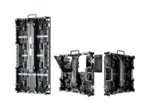
Full front access is the difference between a wall that can be recessed into an architectural surface and one that needs a service corridor behind it. On front-service COB, both the LED modules and the internal control components — power supplies and receiving cards — are removed magnetically from the front, so the wall can sit in a shallow recess with no rear access route.
- It changes the room, not just the wall. Eliminating a rear corridor commonly frees 0.6–1.0 m of floor depth along the wall, which in a control room or a narrow boardroom is often the deciding factor.
- Check module removal clearance in front. A magnetic tool needs working space; a wall behind fixed seating or a lectern may still be effectively immobile despite front access.
- Confirm the route into the building. Cabinet dimensions travel badly: lifts, stair turns and door widths constrain a 600 mm wide cabinet more often than engineers expect, and a wall designed beyond the delivery route is a wall that gets rebuilt on site.
- Ask for the flatness specification. At fine pitch, a 0.5 mm step between adjacent cabinets is visible as a line across a dark scene. Cabinet flatness and the alignment hardware between cabinets matter as much as pitch.
Brightness, refresh rate, processing and budget
The pitch decides how many pixels exist; these four decide whether those pixels look good, get fed properly, and stay affordable to own. A COB wall at any of these pitches is a 600–800 nit, 3,840 Hz-class system, so specification work moves to how it is driven rather than how bright it can go.
- Brightness is about match, not maximum. A 600–800 nit indoor wall run at 40–60% output in a 200–400 lux room reads comfortable and extends component life; running at maximum in a dim room produces glare and eye fatigue. Specify the target brightness for the room and confirm the grey depth available at that level.
- Refresh rate is a camera specification. 3,840 Hz is the baseline for conference and broadcast capture; high-speed and virtual-production work needs 7,680 Hz, and the camera should be tested against the wall rather than trusted to a datasheet.
- Processing is where 4K quotes erode. A native 4K wall needs a sender that accepts 4K at 60 Hz, receiver cards loaded within their pixel ceiling, and fibre for long runs. Our NovaStar sending and processing options guide sets out which platforms suit which wall scales.
- Power scales with density. P0.9 carries 1.78× the pixels per square metre of P1.2 and four times that of P1.8, and the drive electronics scale with them; Market Intelo (2026) estimates COB configurations use 30–40% less power per lumen than equivalent SMD, a supplier-side estimate that should be confirmed against measured figures for the exact build.
- Budget the whole wall, not the panels. A fourfold pixel-count difference across the same area changes panel cost, card count, sender specification and spare-parts holding — the pitch is a system decision, and per-square-metre pricing hides most of it.
COB LED Pixel Pitch Selection Checklist
Before requesting a quotation or confirming a cabinet layout, use the following checklist to establish the project’s requirements.
- Define the application. Identify whether the wall will be used for control room monitoring, corporate presentations, broadcast, commercial advertising, or another indoor application.
- Measure the installation area. Confirm the usable wall width, height, mounting conditions, and available maintenance access.
- Identify the closest viewing position. Record the nearest seating or standing position, along with the typical viewing distance.
- Review the content. Determine whether the wall will show small text, dashboards, technical graphics, standard video, or a mixture of content types.
- Set the native resolution target. Confirm whether Full HD, native 4K, or another resolution is required.
- Compare P0.9, P1.2, P1.5, and P1.8. Evaluate the pixel density, resulting resolution, viewing conditions, and total installed cost for each feasible option.
- Check cabinet dimensions and layout. Verify the actual pixel count of each cabinet and calculate the complete wall resolution.
- Confirm image performance. Review brightness, contrast, grayscale, color consistency, refresh rate, and processing compatibility.
- Verify maintenance requirements. Confirm front or rear service access, spare parts, and repair procedures.
- Evaluate the complete budget. Include installation, processing, commissioning, calibration, and future maintenance.
- Request a product demonstration. Where possible, test the display with representative content at the actual viewing distance.
- Obtain a configuration-specific quotation. Request the cabinet layout, native resolution, technical specifications, accessories, warranty, and delivery details.
This process helps buyers compare solutions based on measurable requirements instead of selecting a pixel pitch from a model name alone.
Frequently Asked Questions
Adhaiwell has manufactured LED and LCD display systems in Shenzhen for more than 15 years, supplying fine-pitch and COB-class walls for control rooms, boardrooms and showrooms across export markets. These are the pitch questions procurement teams raise most often.
Which COB LED pixel pitch is best for a control room?
P1.2 is the default for most control rooms, with P0.9 where operator desks sit within about 2 m of the wall or the room cannot accommodate a 4.8 m wide screen. Control rooms are the application where pitch is least negotiable, because dashboards, maps and 1-pixel chart lines are read continuously rather than viewed. Size the wall backwards from the desk row, then confirm the total pixel count.
Is P0.9 always better than P1.2?
No. P0.9 is better only when the wall must be small or the closest viewer is very near; beyond about 2.5 m the extra density is invisible and the money is better spent on uniformity, control electronics or a larger P1.2 wall. On the same 4K canvas, P0.9 occupies 7.3 m² against 13.0 m² at P1.2 — the premium buys compactness. It also raises the pixel load by 1.78× across the same area, which affects cards, senders and heat.
Can a P1.5 LED wall display native 4K?
Yes, at 6.0 × 3.375 m — 100 cabinets of 384 × 216 pixels, totalling exactly 3,840 × 2,160. Below that size a P1.5 wall cannot hold 8,294,400 pixels and will downscale a 4K source regardless of the player. The wall size, not the pitch, is the operative variable.
What viewing distance do I need for a P1.2 COB LED display?
About 1.2 m is the industry floor for casual viewing, but 2.4 m is a realistic minimum for video and 3.4 m for dashboards and text. The pixel grid stops being resolvable at roughly 4.3 m, which is the distance to design for if the content is dense. Measure the nearest seat rather than averaging across the room.
Does a finer pitch increase power consumption and heat?
Yes, in proportion to pixel density: P0.9 carries 1.78× the pixels per square metre that P1.2 does, and four times what P1.8 does across the same area. COB packaging reduces power per lumen relative to SMD, so the increase is smaller than the pixel ratio suggests, but it still has to be designed for. Ask for measured watts per square metre at your target brightness, and plan the wall cavity airflow around that figure.
The right pitch is the coarsest one that still resolves your content at your nearest seat — everything finer is cost without visible benefit, and everything coarser is a compromise the audience will notice within the first month. Send Adhaiwell the wall width and height, the closest viewing distance, the content type, the resolution target and the destination country, and the configuration — pitch, cabinet count, control chain and mounting — comes back as one specification rather than four separate decisions.