How to design forced-air cooling for an LED display without air conditioning? The answer is not simply to install more fans. For outdoor LED billboards, commercial LED video walls and enclosed digital signage, cooling performance depends on the relationship between heat load, ambient temperature, allowable temperature rise, airflow, static pressure and airflow distribution — a chain that has to be worked through in order, because a weak link anywhere in it produces the same result: a screen that runs hot and fails early.
Technical guide | LED display thermal engineering. Reviewed by the Adhaiwell LED Display Engineering Team.
When a site cannot use air conditioning — no installation space, no power capacity, building restrictions, or an outdoor cabinet with nowhere to mount a refrigeration unit — a properly engineered forced-air system can still remove the heat reliably. What it cannot do is work from a rule of thumb such as “one fan per cabinet” or “X air changes per hour.” This guide sets out the calculation sequence, the fan selection method, the airflow layout rules, the protection and monitoring requirements, and the acceptance criteria that Adhaiwell engineers apply to fan-cooled projects.
Key Takeaways
- Forced-air cooling is designed from the heat load and allowable temperature rise, not from a fan count or a fixed air-change number.
- The required airflow comes from Q = P ÷ (ρ × Cp × ΔT); the margin is then set by the actual system — filter loading, louver and cabinet resistance, solar gain, fan ageing and required redundancy.
- Fans must be selected at their operating point, where the fan curve crosses the system resistance curve. A 5,300 m³/h free-air rating can become roughly 4,500 m³/h once installed.
- Air distribution decides whether cooling works: low intake, high exhaust, internal baffles, and zone-based fan groups on larger screens.
- Measure intake, hot-zone and exhaust temperatures, add N+1 fan redundancy on critical screens, and validate the design under worst-case conditions on site.
Why Does LED Display Cooling Design Start With Heat Load, Not Fan Quantity?
Because the required airflow is a consequence of the heat load and the temperature rise you are willing to allow — decide those two first, and the fans become an output of the calculation rather than a guess.
Where the heat comes from:
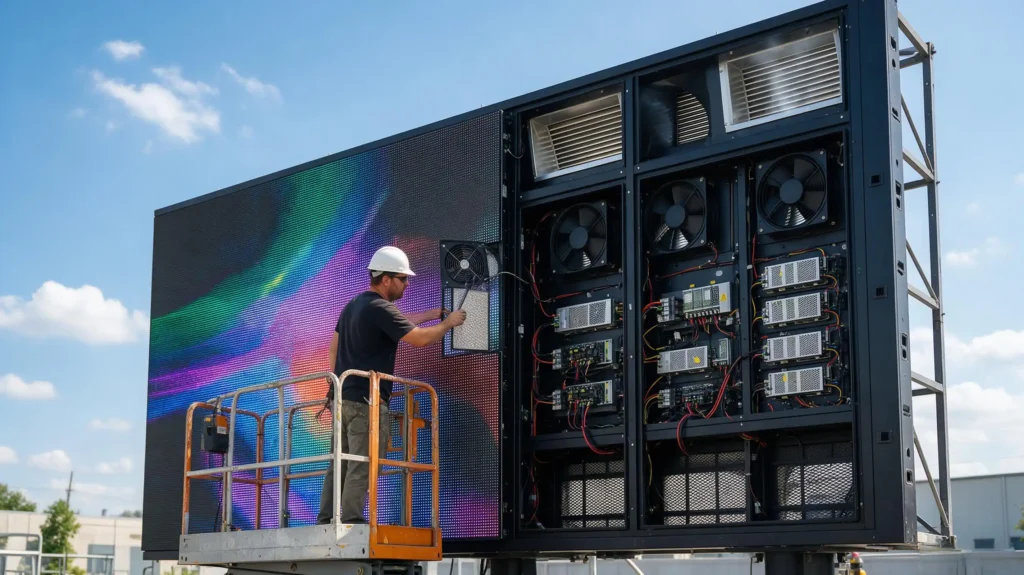
- LED modules and driver ICs — the largest share of the load, and the part whose luminous output and colour stability degrade first with temperature.
- Switching power supplies — the most common service item on an outdoor screen, and a component whose own life is strongly temperature-linked.
- Receiving cards, HUB boards, controllers and auxiliary electronics.
- Solar gain — for outdoor cabinets, an additional heat source that indoor video walls do not have (see below).
What excess temperature does to a screen, in the order it usually appears:
- Brightness loss and colour shift, then isolated dead lamps, then driver IC and power-supply failures, thermal protection trips, intermittent black screens and premature fan failure.
- Field-service guidance from LED Craft (2026, supplier-published) puts the relationship bluntly: every 10 °C above rated operating temperature can roughly halve component life. It is an approximation, not a law — but it is why the same screen model lasts years in one city and months in another.
- Planning guidance from Pixelight (2026) rates switching power supplies at 30,000–50,000 hours for entry-level units and 50,000–80,000 hours for commercial-grade units. Where a unit lands inside that band depends heavily on the air temperature it lives in.
The design sequence that follows:
Heat load → allowable temperature rise → required airflow → system resistance → fan operating point → airflow distribution → protection → monitoring and redundancy → field validation.
Every section below is one link in that chain. Note the framing: the air-change rate does not lead the sequence — it appears later as a cross-check.
How Much Heat Does an LED Display Actually Generate?
The electrical heat load is the screen area multiplied by the design power density — and for outdoor cabinets, solar gain has to be evaluated on top of it.
Electrical heat load: P = S × P_d, where S is screen area (m²) and P_d is design power density (W/m²).
For a 200 m² outdoor display at an assumed 450 W/m² maximum design load:
200 × 450 = 90,000 W, or 90 kW
That is a substantial thermal load before any allowances — and it is the number every later step depends on. Typical design power densities run 220–300 W/m² for indoor screens, 350–450 W/m² for standard outdoor screens, and 450–600 W/m² for high-brightness, high-density builds. Use the manufacturer’s published figure for your specific model, and size on the peak-load condition rather than on average content, because advertising playlists do not stay average.
Does Solar Gain Change the Cooling Load?
Yes — and for outdoor displays it can be significant enough to change the fan count. Forced-air design for an outdoor cabinet cannot assume that electrical heat is the only heat source.
- Direct solar radiation raises the cabinet surface temperature and adds heat to the air path, particularly on dark-coloured or steel enclosures.
- Glass or acrylic enclosures trap heat the way a greenhouse does, so a display mounted behind glass sees a higher effective ambient temperature than the site weather station reports.
- Surrounding surfaces — a sunlit wall, paving or a reflective facade — add reflected radiation and re-radiated heat.
- The most difficult combination is direct sun plus a dark enclosure plus an enclosed rear structure, because all three reduce the temperature difference available for heat to leave through.
The practical response is to reduce solar load before adding airflow: shading structures, lighter surface finishes, ventilated rear voids, and a design ambient temperature measured at the cabinet rather than at the weather station. For screens where the site conditions themselves are still being chosen, the six-factor framework in our guide to choosing the right outdoor LED display for DOOH advertising covers brightness, ingress protection, energy efficiency and thermal exposure together, because these decisions interact.
How Do You Calculate the Airflow an LED Display Needs?
From the sensible-heat relationship between heat load, air density, specific heat and the temperature rise you allow:
Q = P ÷ (ρ × Cp × ΔT) × 3600
where Q is required airflow (m³/h), P is heat load (W), ρ is air density (≈1.2 kg/m³), Cp is the specific heat of air (≈1005 J/kg·K), and ΔT is the allowable air temperature rise above ambient (°C).
Worked calculation: with P = 90,000 W and ΔT = 12 °C:
Q = 90,000 ÷ (1.2 × 1005 × 12) × 3600 ≈ 22,400 m³/h
This is the theoretical airflow required before any allowance for filters, louvers, cabinet resistance, duct losses or fan degradation. It is also the point where many real projects go wrong: a specification that stops here, or that substitutes a rule of thumb, can be undersized by a wide margin.
Where Does ΔT Come From — and Why Not Just Use 42 °C?
The allowable rise should be derived from the components, not from a rule. The chain runs backwards from the most heat-sensitive device in the cabinet:
Lowest component temperature rating → maximum allowable internal air temperature → allowable air temperature rise above design ambient → required airflow.
A practical consequence: if the cabinet air must stay below 55 °C and the design ambient is 45 °C, ΔT is 10 °C, not 20 °C — and the airflow requirement nearly doubles against a cooler site.
Adhaiwell’s own project experience has been that conventional fan cooling is workable at ambient extremes up to about 42 °C on standard screens, and that sites above that figure need reinforced designs. Treat 42 °C as a project-experience boundary rather than an industry limit: the binding constraint is always the temperature rating of the components inside, not the number on the outdoor thermometer.
How Large an Engineering Margin Is Right?
There is no single correct multiplier — the margin has to reflect the specific system, and the drivers should be listed explicitly in the proposal:
- Filter loading: clean versus loaded pressure drop.
- Louver, mesh and grille resistance.
- Cabinet resistance: internal partitions, cable obstructions, narrow rear clearance.
- Solar gain and design-ambient uncertainty.
- Fan ageing and voltage variation over the service life.
- Required redundancy (see N+1 below).
- Site factors: dust, altitude, wind sheltering, exhaust recirculation.
As a preliminary working range, a 1.2–1.5 margin on the theoretical airflow is a reasonable starting point for many projects; it then has to be confirmed against the actual system resistance and the selected fan’s curve. For the 200 m² example that gives a design airflow of roughly 29,000–33,600 m³/h. What a design should not do is apply a fixed multiplier to every project: an oversized fan pack costs more, draws more power and pulls in more dust, while an undersized one fails in the first heat wave. Both errors come from skipping the system-resistance step.
Is Air Change Rate Still Useful?
Yes — as a cross-check, not as the primary criterion. Air change rate (ACH) is airflow divided by effective cabinet volume (ACH = Q ÷ V), and it is useful for comparing cabinet volumes and spotting zones with poor circulation.
To see why it cannot lead the design, run the same 200 m² screen through it. With an average cabinet depth of 0.8 m, V = 200 × 0.8 = 160 m³. At 100 air changes per hour, Q = 160 × 100 = 16,000 m³/h — a figure that sounds generous until you compare it with the 22,400 m³/h the heat balance demands at 90 kW and a 12 °C rise. The air-change figure is simply too low for that load, and no amount of re-reading the airflow number changes it.
Air change rate is a useful secondary check; heat balance determines the primary airflow requirement.
How Do You Select a Fan at Its Real Operating Point?
By intersecting the fan’s performance curve with the system resistance curve — not by reading the airflow number on the datasheet, which describes the fan at zero resistance.
Never select a fan only by its free-air airflow rating. A fan advertised at 5,300 m³/h delivers its rated figure at free air (0 Pa). Installed behind a dust filter, a rain louver, a protective mesh and a narrow cabinet, the back pressure reduces the flow. The actual operating point is where the fan curve crosses the system resistance curve, and both curves belong in the proposal.
This is not a niche detail — it is a documented property of fans in general. ANSI/AMCA Standard 210-25/ASHRAE Standard 51-25 establishes the uniform laboratory methods used to rate fan airflow, pressure, power and efficiency (AMCA International/ASHRAE, 2025), and ASHRAE’s own fan chapter notes that the aerodynamic performance of an installed fan almost always differs from its laboratory rating because of system configuration — elbows, obstructions and abrupt cross-sectional changes in the field installation (ASHRAE Handbook, 2024).
Static pressure — starting points, not specifications. There is no universal static-pressure figure for LED displays; a semi-open cabinet and a fully enclosed outdoor cabinet with filters and louvers are different systems.
| Application | Preliminary static pressure range |
|---|---|
| Open, low-resistance cabinet | 20–30 Pa |
| Enclosed cabinet with filter and louver | 40–80 Pa |
| Narrow airflow path, long duct run | 60–120 Pa or higher |
The final fan selection should be based on the calculated pressure drop of the complete ventilation path.
What to request from the fan supplier:
- Airflow versus static pressure curve, over the full operating range.
- The rated operating point, not just the maximum airflow figure.
- Input power at that operating point.
- Motor temperature rating and bearing type.
- Rated life for continuous duty.
- Noise level (LpA at a stated distance).
- Environmental protection level of the fan itself.
- Speed-control capability and tachometer/alarm output.
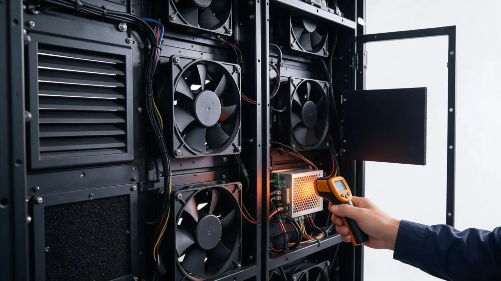
Then ask the question that decides the design: not “how much air can this fan move?”, but “how much air will this fan deliver at the static pressure of my cabinet?”
How Do You Turn Airflow Into a Fan Count?
Divide the design airflow by the fan’s airflow at the operating point, and round up.
Using the 200 m² example: design airflow 29,000–33,600 m³/h; a fan rated 5,300 m³/h at free air that delivers approximately 4,500 m³/h at the cabinet’s operating pressure. At the upper end of the margin:
33,600 ÷ 4,500 ≈ 7.5, so 8 operating fans
and on a critical installation, 9 fans so that a single failure still leaves the required airflow available.
Compare that with the count obtained by dividing 16,000 m³/h by the 5,300 m³/h free-air rating — three fans — and the reason summer blackouts cluster on under-ventilated screens becomes obvious. The gap is not a rounding difference; it is the difference between a design that was calculated and one that was estimated.
What Is N+1 Fan Redundancy and When Do You Need It?
N+1 means installing one more fan than the thermal calculation requires, so that a single fan failure does not immediately cause a thermal failure. For critical DOOH, transport, stadium and public-information screens it is standard practice; for a low-power indoor screen with a generous margin it may be unnecessary. The decision depends on criticality, design ambient, cabinet thermal margin, fan failure rate and maintenance response time.
Where redundancy matters, pair it with monitoring: tachometer feedback or fan-current monitoring per fan, so a stopped fan raises an alarm instead of being discovered by a blackout. A redundant fan that nobody knows has failed is not redundancy.
Where Should Air Enter, Travel and Leave in the Cabinet?
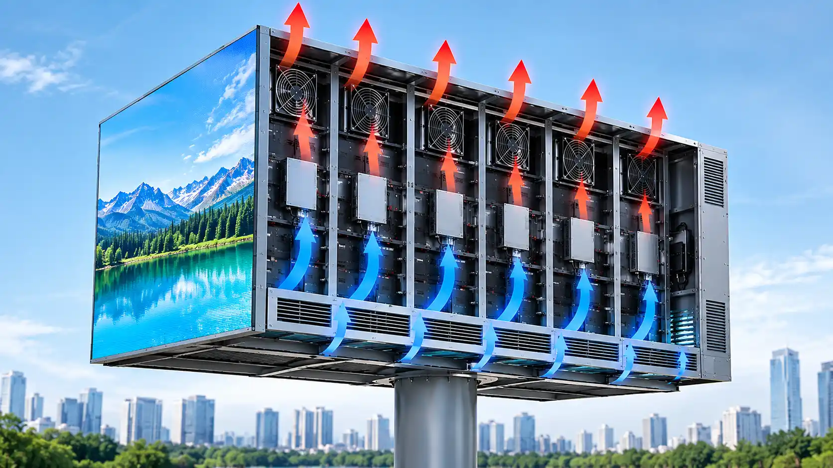
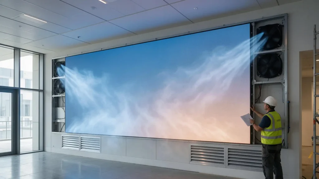
Fresh air in low, across the heat sources, out high — with the path controlled by the cabinet and confirmed by baffles, not left to whichever openings happen to exist.
Distribution decides whether cooling works — not fan count. Two cabinets with identical total airflow can perform completely differently: eight fans clustered on one side leave the far end of a large screen hot, while eight fans distributed across thermal zones move air through every heat-generating region. On large screens, divide the cabinet into zones, each with its own intake, its own heat sources and its own exhaust group.
A typical vertical outdoor LED display uses low-level intake → power supplies and modules → upper cabinet → exhaust fans. The objective is to force fresh air through the areas where heat is actually generated, at the speed the calculation assumed.
Why low intake and high exhaust usually works: hot air rises, so a bottom-to-top path works with buoyancy instead of against it. Forced airflow should still dominate the design — natural convection alone is not sufficient for a high-power screen.
Exhaust or positive-pressure supply? For many outdoor cabinets, exhaust ventilation is the practical configuration: it creates a predictable airflow direction, reduces uncontrolled leakage paths, and keeps components out of a positive-pressure airstream that would drive dust inward. That said, fan direction should follow cabinet geometry and weather protection design rather than a blanket rule — a filtered positive-pressure supply can be the right answer where clean-air delivery to specific components matters. Control the airflow path rather than fixating on “blow” or “suck.”
How Do You Size Intake and Exhaust Openings?
Use the opening-area relationship A = Q ÷ (3600 × u), where A is the free opening area (m²), Q is the airflow through that opening (m³/h) and u is the design air velocity (m/s).
For an opening handling 5,000 m³/h at a target velocity of 1.5 m/s:
A = 5000 ÷ (3600 × 1.5) ≈ 0.93 m² of free area
Then convert to physical dimensions. A louver or filter may present only 50–80% free area, so 0.93 m² of free area can require roughly 1.2–1.9 m² of gross opening. Undersized openings are one of the most common causes of under-performing ventilation systems, because the fan is fighting a restriction the drawing did not show.
What Causes Airflow Short-Circuiting?
Short-circuiting is when air travels from intake to exhaust with very little of it passing the heat sources — the airflow reading looks healthy while the cabinet still runs hot. Common causes:
- Intake and exhaust openings placed close together, often on the same face.
- Missing internal partitions in a large cabinet cavity.
- Oversized empty volumes that let air bypass the module rows.
- Fans positioned without reference to where the heat actually is.
- Unsealed cable entries, gaps in the frame and uncontrolled openings.
- Exhaust air returning to the intake because of wind direction or a recessed mounting.
Fix the layout, not the fan count: baffles and partitions that force air through the thermal zone usually recover more performance than adding another fan to a short-circuited cabinet.
Layout by Mounting Scenario
- Pole-mounted or freestanding screens: exhaust fans in a row across the top rear rail, with a continuous strip intake across the bottom, so air crosses the power supplies, driver ICs and module rows over the full cabinet height.
- Wall-mounted screens: symmetric exhaust fans at the upper rear corners, intakes at the lower rear or lower sides; where the rear clearance is under 15 cm, use a diagonal path (intake bottom-left, exhaust top-right) and avoid same-side in-and-out.
- Ceiling-hung screens: exhaust fan centered at the top rear, intake on the upper rear, and relief openings at the bottom sides so heat does not pool in the sealed ceiling void above.
How Do You Protect the Airflow Path From Rain, Dust and Sun?
Ventilation creates a conflict — the cabinet needs airflow, and the electronics need protection — and the answer is a properly engineered ventilation assembly, not a sealed cabinet.
The assembly should include rain louvers with drip edges, drainage paths and base drainage holes, dust filters and protective mesh, and serviceable filter access. The protection level of the complete path matters more than the rating of any single part: IEC 60529 defines the IP Code used to classify enclosure protection against access to hazardous parts and against ingress of solid foreign objects and water (International Electrotechnical Commission), and an IP-rated fan or louver inside a poorly designed opening can still admit water. Select ventilation components with an environmental protection level suited to the site — IP44 minimum indoors, IP54 outdoors is a common specification — but treat the rating as one input to the design rather than a substitute for it.
Filters are part of the thermal design, not an accessory. A clean filter and a loaded filter are two different ventilation systems:
Pressure drop up → airflow down → cabinet temperature up.
So the thermal calculation should account for new-filter pressure drop, loaded-filter pressure drop, the replacement interval, and how easily a technician can reach the filters. In dusty environments, an unmaintainable filter is not a filter — it is a scheduled overheating event.
Sun and water management beyond the vents: tilted louver blades to shed water, drainage that does not route water across electrical components, an external shade or ventilated cladding on exposed faces, and intake positions that avoid drawing in air pre-heated by a sunlit surface.
What Monitoring, Control and Shutdown Logic Does a Fan-Cooled Display Need?
Enough instrumentation to know the actual temperature rise and to react before components are damaged — typically four sensors plus fan feedback.
Sensor locations:
- Intake air — the actual cooling-air temperature, which is often higher than the site ambient figure.
- Hot-zone air — inside the cabinet, near the power supplies and driver boards.
- Exhaust air — the air leaving the thermal zone.
- Critical component — for example the power supply or control board, measured at the device.
With intake and exhaust readings you can calculate the real rise, ΔT = T_exhaust − T_intake, and compare it with the value the design assumed. A rise that keeps growing is the earliest available warning that a filter is loading up or a fan has slowed.
Control logic, not a universal set point. Rather than publishing fixed thresholds as a standard, define the logic and derive the numbers from the lowest temperature-rated component in the thermal chain:
| Condition | Fan response |
|---|---|
| Cabinet air below the start threshold | Off, or low speed |
| Normal operating band | Variable speed, tracking temperature |
| Above design rise | High speed |
| Thermal alarm threshold | Full speed plus alarm to the control room |
| Critical temperature | Protective action per the equipment design |
A typical starting configuration on Adhaiwell projects has been start at 32 °C, full speed at 42 °C and stop below 28 °C — useful as a default, but it must be adjusted to the actual component ratings, because those ratings, not the default, govern the safe limit. Running fans continuously is not a safer choice: it wastes power, loads the filters faster and, in cool humid conditions, drives condensation cycles that corrode driver boards. Variable-speed control reduces energy consumption, noise, dust intake and fan wear at the same time. IEC 62368-1, the product safety standard for audio/video, IT and communication equipment, addresses safety hazards rather than prescribing a display cooling temperature (International Electrotechnical Commission) — the thermal limits come from the component datasheets.
Fan hardware standard for 24/7 outdoor duty:
- Environmental protection matched to the site (IP44 minimum indoors, IP54 outdoors as a common baseline).
- Operating range covering the site’s extremes; −20 to +70 °C covers most installations.
- Rated life of 50,000 hours or more for continuous duty.
- Noise at or below roughly 45 dB per fan for commercial and municipal locations.
How Do You Prove the Cooling Design Works on Site?
By defining measurable acceptance criteria before installation, then measuring them under the worst conditions the site can produce — a summer afternoon with the screen at full brightness.
Thermal criteria: maximum cabinet air temperature within the design limit; measured air temperature rise within the calculated ΔT; no significant thermal dead zones; power supplies, driver boards and control cards within their manufacturer-specified temperature limits.
Airflow criteria: required airflow achieved at the actual system pressure; intake and exhaust flows balanced; no major short-circuiting between supply and return.
Reliability criteria: a fan failure raises an alarm; filters are reachable for cleaning and replacement; drainage functions after rain; and after a single fan failure the screen still holds its required operating margin where N+1 was specified.
Commissioning measurements to record: intake air temperature, exhaust air temperature, hot-zone air temperature, component surface temperatures at the power supply and driver boards, hotspot readings across the screen face, total airflow, fan speed, pressure differential and alarm status.
Then keep it valid. Filters are washed monthly in dusty environments, fans and vents inspected every six months, and internal temperature alarms logged rather than silenced. The rhythms and component service expectations for the wider display are set out in our outdoor LED display installation and maintenance guide; the point here is that a fan-cooled design is only as good as its maintenance schedule, because the airflow margin is what the schedule protects.
When Is Forced-Air Cooling Not Enough — and What Should You Specify From a Manufacturer?
When the heat load, the ambient temperature or the cabinet geometry pushes the required airflow beyond what the structure can carry, or when component limits simply cannot be met, fans stop being the answer and the cooling strategy has to change.
Preliminary framework by display type:
| LED display | Typical approach |
|---|---|
| Small display | Natural ventilation plus auxiliary forced exhaust |
| Medium display | Distributed forced-air cooling |
| Large display | Zoned forced-air cooling, one fan group per thermal zone |
| High-power fine-pitch display | Detailed thermal analysis |
| High-temperature outdoor display | Forced air plus shading plus enhanced airflow |
| Fully enclosed high-power display | Detailed thermal simulation or an alternative cooling method |
There is no universal area at which air cooling becomes impossible — a well-ventilated 100 m² screen with moderate power density can be easier to cool than a sealed 20 m² cabinet with high brightness.
Consider a different strategy when the internal heat load or ambient temperature is extreme, solar exposure is severe, the cabinet is fully sealed, ventilation space is insufficient, exhaust air recirculates into the intake, the required airflow becomes impractically large, noise limits prevent adequate fan operation, or component temperature limits cannot be maintained. The alternatives include air conditioning, heat exchangers, improved cabinet construction, lower-power modules or reduced brightness operation, shading, larger ventilation channels and additional thermal zones. In some projects, reducing heat generation is more effective than increasing fan capacity — a point worth raising before the cabinet is ordered rather than after.
What to require from a supplier on a no-AC project:
- A heat-balance calculation and an air-change cross-check for your specific screen, not a generic fan quantity.
- The system resistance calculation and the fan curve, with the operating point marked on it.
- Published thermal operating limits for the exact cabinet model (Adhaiwell’s aluminium-profile range, for example, is published at −20 to +65 °C).
- 72-hour burn-in before shipment with the fan and thermostat loop exercised, not only the display.
- Filter access a technician can reach without removing modules, and a spare-fan kit in the spare-parts package.
- Commissioning support that includes a summer-peak temperature check and alarm verification.
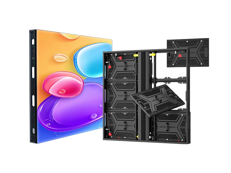
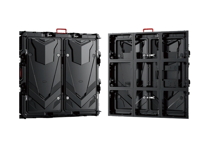
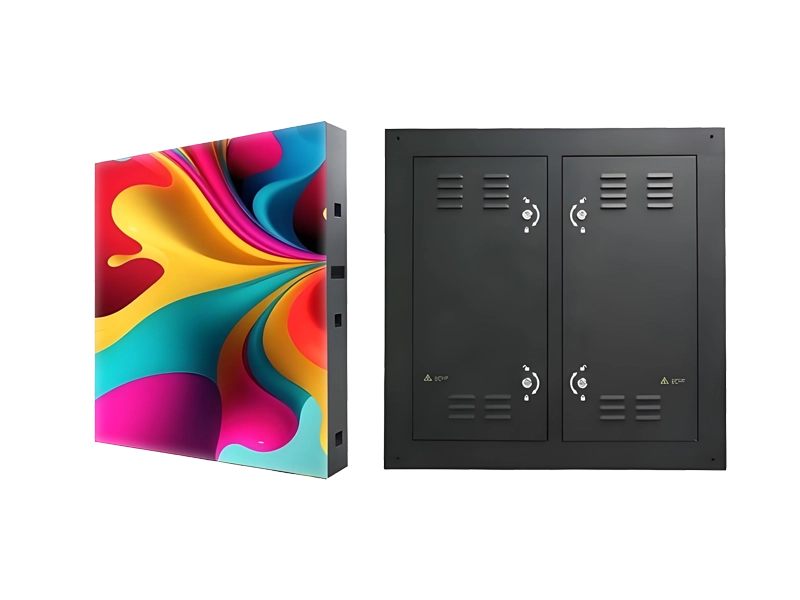
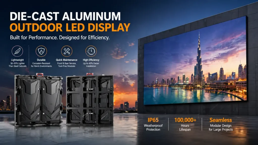
Two cabinet architectures illustrate how much the thermal decision drives everything else. The die-cast aluminium outdoor LED display uses dual high-velocity fans plus an aluminium heat sink and is published at 300 W/m² average and 800 W/m² maximum power — an active-cooling platform for higher density and hotter sites. The fanless aluminium-profile outdoor LED display cabinets cool entirely through extruded fins, published at −20 to +65 °C with 200 W/m² average and 650 W/m² maximum power — a passive platform that removes fans, filters and filter maintenance from the ownership equation entirely. Neither is universally better; the calculation decides which one fits the site.
Need a cooling design for a custom LED display? Share the screen dimensions, cabinet depth, LED power density, maximum ambient temperature and installation environment, and the Adhaiwell engineering team can evaluate the thermal load, airflow requirement, fan configuration and ventilation layout before production — see our outdoor and indoor LED display solutions or request a project consultation.
FAQ: Forced-Air Cooling for LED Displays
Adhaiwell has manufactured LED and LCD displays in Shenzhen for more than 15 years, including projects where property rules, facade restrictions or power budgets ruled out air conditioning entirely. The answers below come from that project record and from the calculations above.
Can an LED display work without air conditioning?
Yes, in many applications — natural ventilation or forced-air cooling is viable when the heat load, design ambient temperature, allowable temperature rise and cabinet airflow path are properly engineered. It is not viable for every screen: large high-power billboards, fully enclosed cabinets and extreme-temperature sites may need zoned cooling, shading or another method.
How do I calculate the required airflow for an LED display?
Start with Q = P ÷ (ρ × Cp × ΔT) × 3600 to get the theoretical airflow from the heat load and allowable rise, then apply a project-specific margin for filter loading, system resistance, solar gain, fan ageing and redundancy. Confirm the final figure against the selected fan’s curve at the calculated system pressure.
Is CFM or m³/h better for fan selection?
Neither unit is better — what matters is the airflow the fan actually delivers at the required static pressure. US projects commonly work in CFM, many international projects in m³/h; convert rather than compare, and always compare at the same operating point.
How many fans does an LED display need?
There is no reliable universal number. Fan count follows design airflow divided by airflow at the operating point, rounded up, then adjusted for zoning and redundancy. A 200 m² screen at 90 kW thermal load can move from three fans by rule of thumb to eight by calculation.
Should LED display fans blow air in or exhaust it out?
Both configurations are used. For many outdoor cabinets, exhaust ventilation with controlled low-level intake gives a predictable path and keeps dust out of the electronics; filtered positive-pressure supply suits some layouts. Decide from cabinet geometry, weather protection and component layout rather than a blanket rule.
Does a higher air change rate always mean better cooling?
No. Air change rate is a cross-check on ventilation and a useful way to compare cabinet volumes, but a high ACH does not guarantee that air reaches the hottest components or that the heat load is removed. Heat balance determines the airflow requirement.
Should an outdoor LED display use dust filters?
In dusty environments filters protect the electronics, and their pressure drop must be included in the fan and system design — clean and loaded conditions both. A filter that cannot be reached for cleaning will degrade airflow until the screen overheats.
How can I keep a fan failure from shutting down the screen?
Use N+1 fan redundancy on critical screens, monitor fan speed or current per fan, and set a temperature alarm that triggers before component limits are reached. The redundancy margin is only useful if a failed fan is detected.